Sometimes, you might want to use a microcontroller to do something simple, but not only are chips like the ATmega328P (Arduino Uno’s IC), they are also fairly expensive. That’s why using AVR chips from the ATtiny family are great. The ATtiny13A only has 64 BYTES (not kilobytes… bytes) of RAM and 1KB of flash, but with 6 I/O pins, that can still be plenty for many applications. They only cost about $.50 per chip, making it very inexpensive to create several circuits with them.
Now it’s the big leagues, as it’s time to move away from the comfort of the Arduino IDE and into the world of assembly and direct register manipulations. While it is technically possible to use the Arduino IDE, Atmel Studio is the better option. It is an industry standard IDE for programming AVR microcontrollers, and it also has helpful features such as a debugger and pre-made register definitions. To install it, go to this page and click the download button. Once it has been successfully installed, run it. You’ll be greeted by the Start Page. Click on New Project and select Assembler/AVR Assembler Project.
Name it “blink” and put it inside of a familiar directory. Then search for Attiny13a and select it. This will include its device properties and register definitions.
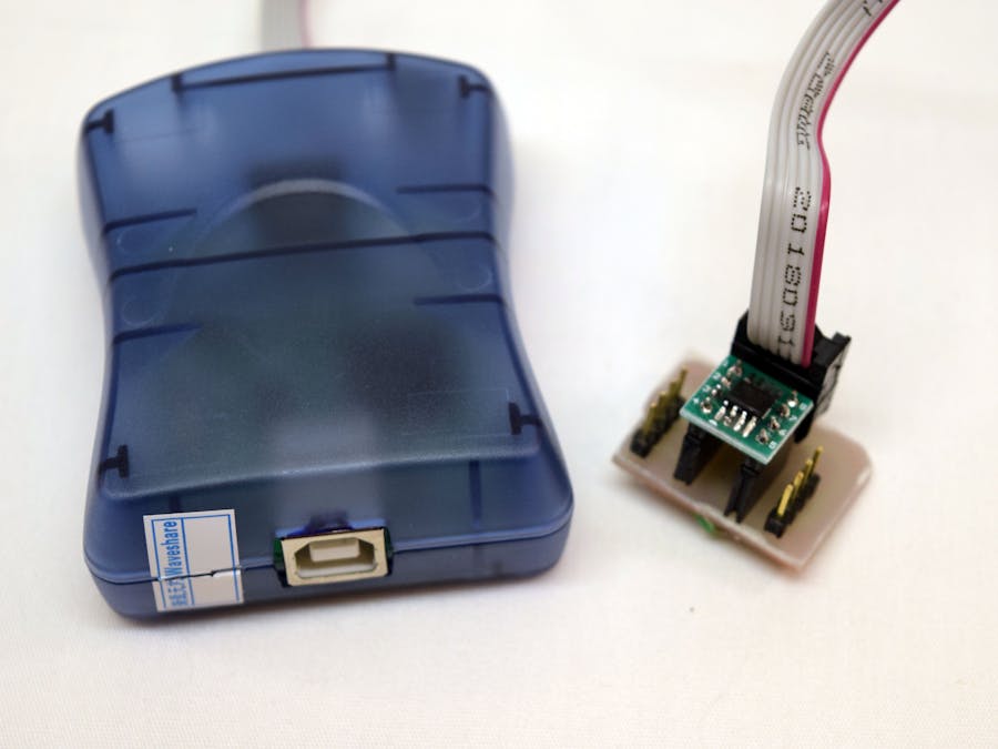
For this project, I went with an AVRISP MkII programmer due to its relatively low cost ($40) and ease of use when interfacing.
It has a 6-pin header that connects to the ICSP header on development boards. Below is the Arduino Uno’s header:
Those pins include MISO, MOSI, SCK, RESET, GND, and VCC. The programmer sends and receives data from the chip that can be viewed in Atmel Studio.
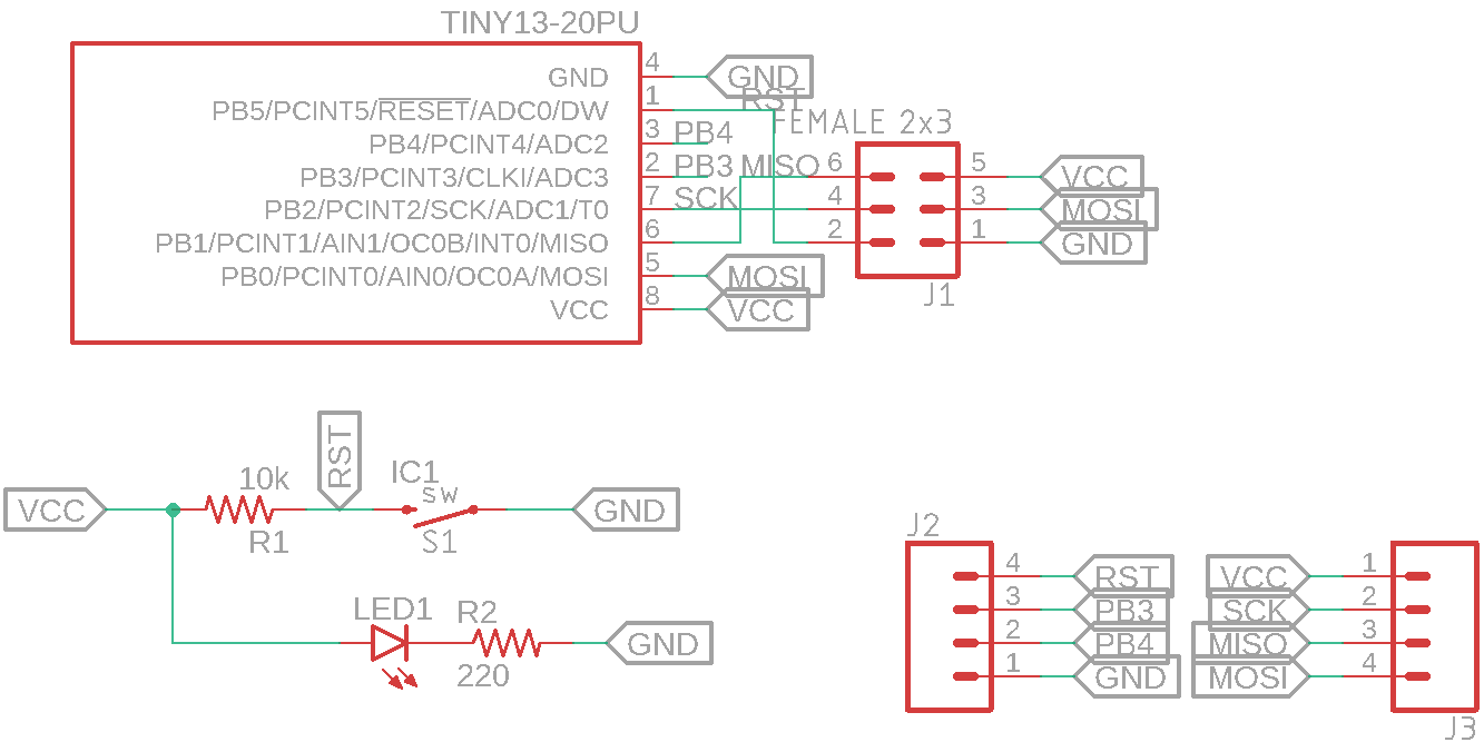
Although the ATtiny13A has the pins needed for ICSP, it doesn’t have a readily available development board, so I had to create a custom breakout PCB for it. I began by making a new schematic in Eagle and adding an ATtiny13A from the atmel library, along with a few pin headers and resistors/switch and LED.
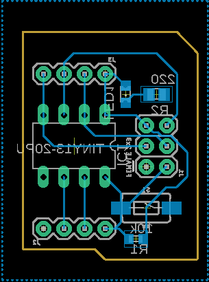
Then I connected them together as seen below and designed a single-layer PCB.
I then generated G-Code using ChiliPeppr and milled it with a CNC router, but unfortunately, many of the traces got milled as well due to a misconfiguration.
This cause me to have to solder many of the wires by hand. But after some testing, everything worked as expected.
The datasheet is your friend. It tells you the specifications, registers, and instructions to execute to accomplish certain tasks. To blink an LED, it is necessary to know how to output signals on an I/O pin, along with how to branch and setup the IC after a reset. According to the datasheet, the first vector at 0x00 handles what to do at startup, so we can set the device to branch to the start of the program.
To set PB3 as an output, the Data Direction Register (DDRB) must be set to a 1 at the 4th bit from the right.
Additionally, it can be set high or low by changing the 4th bit in the PORTB register.
Timing can be done by cycling for a certain number of clocks and then exiting the loop once it reaches the target amount.
Program FlowAt the start of the program, the reset vector is set to start at the beginning of the program, where it enters the init label. Registers r16 through r25 are general-purpose 8-bit registers that can have literals loaded in directly, so most programs use register numbers starting at r16.
A value of 0b00001000 is loaded into DDRB, setting PB3 to an output. Next, the program enters the loop label, where the chip alternates between setting PB3’s value bit to 0 and 1. At each alternation, it jumps to the timer labels which count a certain amount of times which correspond to the amount of delay, essentially wasting clock cycles. After that number has been reached, the program jumps back to the main loop.
Programming is simple in Atmel Studio. First, build the program and output the hex file by pressing F7. Then, all you have to do is open up the Device Programming window by going to Tools -> Device Programming and selecting the Memories tab. Now you can click Program to flash the hex file to the chip.
To blink the LED, attach its anode to PB3 (pin 2), and its cathode to GND (pin 4). It should turn on for about one second, then off for one second, and continue to loop in that pattern.
Since the ATtiny13A is so cheap, I plan on showing what kinds of applications it can be used in, such as a simple device that can tell when a user presses a button and then buzzes.


Comments
Please log in or sign up to comment.